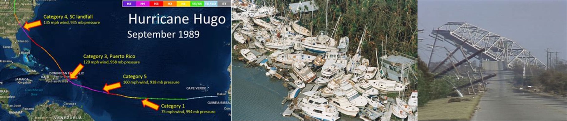
September 22, 1989, 12:30 AM. Hurricane Hugo made landfall near Charleston, South Carolina, with sustained winds of 140 mph, becoming one of the most devastating hurricanes to strike the U.S. East Coast. As the storm surge receded and the winds calmed, investigators discovered a disturbing pattern: while many buildings' main structural systems survived, their windows, curtain walls, and cladding systems had failed catastrophically, turning glass fragments into deadly projectiles.
The hurricane's aftermath revealed a fundamental flaw in how engineers understood wind loading differences between structural systems and building components. Main Wind Force Resisting Systems (MWFRS) designed to carry overall building loads had performed reasonably well, but Components and Cladding (C&C) elements experienced pressures far exceeding those predicted by simplified analysis methods of the era.
Hurricane Hugo's destruction catalyzed a revolution in component design methodology, demonstrating that windows, wall panels, and roofing systems experience fundamentally different wind loading patterns than the structural frames that support them. The disaster exposed how tributary area effects, local pressure amplifications, and dynamic response characteristics create loading conditions that require entirely separate analysis approaches.
p_component = q × G × C_p × (area_effect)
This basic component pressure relationship appeared adequate until Hugo revealed that area effects and pressure coefficients for small building elements differed dramatically from those governing overall structural response, leading to the development of specialized C&C design methodologies.
The Engineering Foundation: Understanding Component vs. System Response
The Engineering Foundation: Understanding Component vs. System Response
The fundamental distinction between Components and Cladding (C&C) and Main Wind Force Resisting Systems (MWFRS) represents one of the most important advances in modern wind engineering. ASCE 7-10's simplified method for C&C design provides a systematic approach to this complex phenomenon while remaining accessible to practicing engineers who design the building envelope elements that provide the first line of defense against wind forces.
The physical basis for different C&C and MWFRS loading lies in how atmospheric turbulence interacts with building elements of different sizes. Large structural systems respond to average wind pressures over substantial areas and time periods, while small components experience peak pressures from individual wind gusts that may last only seconds but create forces far exceeding those affecting the overall structure.
Tributary area effects govern this fundamental difference through statistical principles that recognize how peak wind pressures vary inversely with the area over which they act. A small window experiences the full intensity of local pressure peaks, while a large wall system sees these peaks averaged over substantial areas where maximum pressures cannot occur simultaneously across the entire surface.
C_p,net = C_p,external - C_p,internal × area_factor
This net pressure coefficient relationship demonstrates how external and internal pressures combine differently for components versus systems, with area factors that account for the reduced probability of peak pressures occurring simultaneously over large areas.
The ASCE 7-10 simplified method addresses these complexities through pressure coefficients and adjustment factors derived from extensive wind tunnel testing and statistical analysis of atmospheric turbulence. The method recognizes different zones on building surfaces where local acceleration effects, corner vortices, and separation phenomena create pressure amplifications that affect components differently than overall structural response.
p_net30 = q_h × [(G × C_p) - (G × C_pi)] × zone_factor
Where p_net30 represents the net design pressure for C&C, q_h is the velocity pressure at mean roof height, G accounts for gust effects, and zone factors address local pressure amplifications in different areas of the building envelope.
Edge and corner effects create particularly severe loading conditions for C&C elements, as flow separation and acceleration around building edges generate suction pressures that can exceed windward pressures by factors of 2.0 or more. These effects diminish with distance from edges, creating pressure zones that require different design values depending on component location.
Zone_1: High pressure zones (corners, edges)
Zone_2: Intermediate zones
Zone_3: Interior zones (lowest pressures)
This zone classification system provides a systematic approach to accounting for local pressure amplifications while maintaining design simplicity for routine applications.
Real-World Applications: Where C&C Design Saves Lives and Property
Real-World Applications: Where C&C Design Saves Lives and Property
Components and Cladding design methodology has become essential for protecting building occupants and maintaining structural envelope integrity during extreme wind events. From residential windows to commercial curtain wall systems, proper C&C analysis ensures that building envelopes can resist the intense local pressures that develop during hurricanes and severe storms.
Curtain wall design in high-rise construction presents particularly demanding C&C applications where large glass panels must resist extreme pressures while maintaining architectural appearance and energy performance requirements. Modern curtain walls often feature minimal structural depth and maximum glazing area, creating design challenges that require sophisticated understanding of local pressure effects and dynamic response characteristics.
Residential construction relies heavily on ASCE 7-10 C&C provisions for designing windows, doors, and roofing systems that protect homes during hurricanes and severe storms. The simplified method enables rapid evaluation of standard residential components while providing the technical rigor necessary for life safety protection.
Our repository's ASCE 7-10 Ch30 Part 2 Components and Cladding Simplified Method calculation (downloaded over 1,069 times with a 5.0-star rating), developed by community contributors, addresses these complex design scenarios through comprehensive implementation of zone factors, pressure coefficients, and tributary area effects that govern C&C performance.
Industrial facility design demands C&C analysis for large roof and wall panels that must resist both positive and negative pressures while supporting equipment loads and maintaining weathertightness. Manufacturing facilities often feature large, lightly framed enclosure systems that depend entirely on proper C&C design for structural adequacy.
Educational and institutional construction frequently involves complex building geometries with multiple roof levels, architectural features, and large glazed areas that create challenging C&C design scenarios. Schools, hospitals, and office buildings must maintain envelope integrity to protect occupants and maintain emergency operations during extreme weather events.
Coastal construction presents unique C&C challenges where hurricane-force winds combine with corrosive salt spray and potential debris impact to create demanding service conditions. The simplified method provides guidance for designing building envelopes that can survive these extreme environments while maintaining long-term durability.
Agricultural and warehouse construction utilizes C&C provisions for designing large, economical enclosure systems with minimal structural framing. Metal building systems rely heavily on proper C&C analysis to ensure that roof and wall panels can resist local pressure effects without excessive material usage or construction cost.
Shopping centers and big-box retail construction often feature extensive flat roofs with minimal parapets that create challenging C&C design conditions. The simplified method addresses these applications through specific guidance for low-slope roofs and the pressure amplifications that develop in corner and edge regions.
The Hidden Complexity: Why Components Experience Different Wind Worlds
The Hidden Complexity: Why Components Experience Different Wind Worlds
The fundamental difference between component and system response to wind loading involves sophisticated atmospheric and structural phenomena that challenge engineering intuition. What appears as uniform wind pressure actually consists of complex, rapidly varying pressure fields that affect building elements differently depending on their size, location, and dynamic characteristics.
Atmospheric turbulence creates pressure fluctuations that occur over multiple time and length scales, from large weather systems that affect entire buildings to small eddies that create intense local pressures lasting only seconds. Components respond to the full spectrum of this turbulence, while structural systems filter out high-frequency variations through their mass and stiffness characteristics.
p_fluctuating(t) = p_mean + Σ[p_gust,i × sin(ω_i × t + φ_i)]
This pressure fluctuation relationship demonstrates how atmospheric turbulence creates time-varying pressures with multiple frequency components that affect components and systems differently based on their dynamic response characteristics and tributary areas.
Building aerodynamics introduce local flow phenomena that create pressure patterns completely different from the uniform pressure distributions assumed in simplified analysis. Corner accelerations, roof edge separations, and wall surface boundary layers all create localized pressure amplifications that can exceed mean pressures by factors of 3.0 or more.
While these equations look intimidating on paper, our XLC add-in displays them as easily readable mathematical equations directly in Excel, transforming the complex pressure distribution requirements of ASCE 7-10 C&C analysis into practical design tools that engineers can confidently apply without requiring specialized wind tunnel testing or computational fluid dynamics analysis.
Statistical effects govern how peak pressures vary with area and duration, creating the fundamental basis for different C&C and MWFRS design approaches. Large areas cannot experience peak pressures simultaneously across their entire surface, while small components see the full intensity of local pressure peaks that may be statistically independent of pressures on adjacent elements.
p_peak,area = p_peak,point × √(area_reference / area_actual)
This area reduction relationship demonstrates how peak pressures decrease with increasing area through statistical averaging effects that reflect the spatial correlation of atmospheric turbulence, providing the theoretical basis for different design approaches for components versus systems.
Dynamic amplification effects can increase component response beyond static pressure predictions when natural frequencies approach those of atmospheric turbulence. Flexible components may experience resonance effects that amplify static pressure loads, while rigid elements respond primarily to quasi-static pressure loading.
Pressure equalization systems in building envelopes create additional complexity as internal pressures interact with external pressures in ways that depend on opening configurations, compartmentalization, and the dynamic characteristics of pressure relief systems. These interactions can either increase or decrease net component loads depending on system design and operation.
Installation and construction details significantly affect actual component performance compared to idealized design assumptions. Gasket compression, thermal movement, and construction tolerances all influence how components actually respond to wind loading, potentially creating failure modes that differ from those predicted by design calculations.
Professional Approach: Implementing C&C Design for Building Envelope Reliability
Professional Approach: Implementing C&C Design for Building Envelope Reliability
The critical nature of building envelope performance demands systematic professional approaches to C&C design that address not only ultimate strength requirements but also serviceability, durability, and the complex interactions between different envelope systems that determine overall building performance during extreme wind events.
The ExcelCalcs community shares a passion for making accurate calculations with MS Excel, providing a platform where engineers can access expert knowledge through our comments feature and benefit from collective experience with C&C applications across diverse building types from residential construction to complex commercial curtain wall systems.
Professional C&C design begins with accurate building classification and zone determination that reflects actual building geometry and local wind exposure conditions. The simplified method's zone factors depend critically on proper identification of edge distances, corner regions, and the geometric parameters that determine pressure coefficient applicability.
Pressure coefficient selection requires understanding the physical basis for different values and their appropriate application ranges. The simplified method provides tabulated values for common building configurations, but engineers must understand when these values apply and when more detailed analysis becomes necessary for unusual geometries or critical applications.
Our repository's worked solutions give engineers a head start in implementing ASCE 7-10's C&C methodology while building on existing Excel skills with a much faster learning curve than specialized envelope engineering software that requires extensive training and may not provide adequate transparency in calculation procedures and assumptions.
Load path analysis becomes essential for ensuring that C&C design pressures can be effectively transferred through the building envelope to the structural system. Component design is meaningless if attachment systems cannot transfer design loads or if load paths involve elements not designed for the resulting forces.
Quality assurance procedures must verify that design assumptions remain valid throughout the project lifecycle, including construction modifications, operational changes, and maintenance activities that might affect component performance. The complexity of modern building envelopes creates numerous opportunities for construction details to compromise design intent.
Integration with other building systems requires coordination between C&C design and mechanical, electrical, and plumbing systems that penetrate the building envelope. These penetrations can create local pressure effects and load path discontinuities that affect component performance in ways that require careful analysis and detailing.
Documentation standards require clear presentation of C&C analysis assumptions, design pressures, and load paths that enable proper construction and long-term maintenance. Quality assurance through comments feature and peer review helps ensure that design intent is properly communicated and maintained throughout project delivery.
Repository Showcase: Comprehensive ASCE 7-10 Wind Analysis Solutions
Repository Showcase: Comprehensive ASCE 7-10 Wind Analysis Solutions
Beyond our flagship ASCE 7-10 Ch30 Part 2 Components and Cladding analysis, engineers can access related calculations including ASCE710W - ASCE 7-10 CODE WIND ANALYSIS PROGRAM (1,185 downloads, 4.5-star rating), ASCE 7-10 Ch28 Method 2 - Simple Diaphragm Low-Rise Buildings (964 downloads, 3.4-star rating), and Snow Loads ASCE 7-10 for comprehensive environmental loading (510 downloads, 4.3-star rating).
For specialized applications, our repository includes ASCE 7-10 CODE SNOW LOAD ANALYSIS PROGRAM (426 downloads, 4.4-star rating), ASCE710E for seismic analysis (438 downloads, 4.4-star rating), and ASCE 7-10 Load Combinations (408 downloads, 3.9-star rating). Building classification requirements are addressed through ASCE 7-10 ENCLOSURE (224 downloads, 3.5-star rating), while topographic considerations utilize Topographic Wind Factor Kzt_ASCE 7-10 (107 downloads, 5.0-star rating). Environmental loading analysis includes ASCE 7-10 CODE ICE LOAD ANALYSIS PROGRAM for comprehensive weather considerations (202 downloads, 3.9-star rating). International practitioners can access Wind Load Eurocode 1 for European applications (133 downloads, 4.3-star rating). This diversity ensures that regardless of your specific C&C application or building type, our community has developed comprehensive solutions to meet your envelope design requirements.
Advanced wind analysis tools include Wind Loading on a Flexible Steel Member for dynamic considerations (143 downloads, 4.5-star rating), Wind Loads on Gable Frame to Australian Wind Code AS1170.2 for international applications (638 downloads, 3.8-star rating), and Wind Actions.xls for general analysis (532 downloads, 4.3-star rating). The comprehensive nature of our ASCE 7-10 library reflects decades of collective engineering experience with both C&C and MWFRS analysis across diverse building applications and geographic regions.
Start Your C&C Design Journey Today
Start Your C&C Design Journey Today
The complexity of modern building envelope design demands calculation tools that implement ASCE 7-10's sophisticated C&C methodology while remaining accessible to practicing engineers. Our ASCE 7-10 Ch30 Part 2 Components and Cladding Simplified Method calculation represents the culmination of extensive community development, incorporating zone factors, pressure coefficients, and tributary area effects into a comprehensive analysis tool that handles the complexity of C&C design requirements.
We extend our appreciation to the engineering contributors who developed these essential calculation tools, transforming the sophisticated requirements of ASCE 7-10 C&C provisions into practical design solutions that serve engineers worldwide. Their expertise has created calculation templates that continue to evolve with industry advances and incorporate lessons learned from both successful building envelope performance and documented failures from extreme wind events.
Join the ExcelCalcs community with a $99 professional subscription—insignificant compared to MathCAD, Mathematica, or Maple—and gain access to our complete repository of ASCE 7-10 analysis solutions. Students and educators benefit from our 50% academic discount, while free trials allow you to explore the comprehensive capabilities of our C&C calculation tools without commitment.
Join the ExcelCalcs community today and discover why thousands of engineers trust our templates for their most critical building envelope design challenges. Because when components and cladding must protect building occupants from nature's fury, you need calculations that understand the sophisticated engineering behind the simplified method.