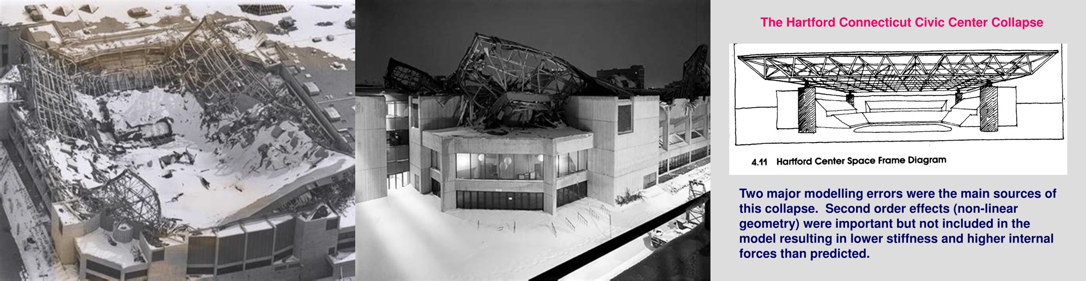
On January 18, 1978, at 4:19 AM, the Hartford Civic Center's massive roof collapsed under the weight of heavy snow and ice, pancaking into the arena below. Miraculously, the collapse occurred just six hours after 5,000 basketball fans had left the building following a University of Connecticut game. The disaster was traced to a fundamental misunderstanding of how structural members behave when subjected to both compression and bending forces simultaneously—a phenomenon engineers call beam-column interaction.
The space frame supporting the 300-foot by 360-foot roof contained members that were designed to carry primarily compressive loads, but the design failed to adequately account for the combined effects of axial compression and lateral bending moments. Under these combined stresses, the critical relationship becomes:
P/P_allow + M/M_allow ≤ 1.0
Where P is the applied axial load, M is the applied moment, and the allowable values represent the capacity under pure loading conditions. When this interaction equation exceeds unity, as it did that snowy night in Hartford, catastrophic failure becomes inevitable.
The Engineering Foundation: Understanding Beam-Column Behavior
When structural members experience both axial compression and bending moments simultaneously, they exhibit complex behavior that cannot be predicted by analyzing each load type independently. This interaction effect occurs because compression forces reduce a member's ability to resist bending, while bending moments can trigger premature buckling under compression loads.
The fundamental governing equation for beam-column interaction under AISC specifications is:
P_r/P_c + 8/9 × (M_rx/M_cx + M_ry/M_cy) ≤ 1.0 (when P_r/P_c ≥ 0.2)
Where P_r is the required axial strength, P_c is the available axial strength, M_rx and M_ry are the required flexural strengths about the x and y axes, and M_cx and M_cy are the available flexural strengths about the respective axes.
For members with lower axial loads, the interaction equation becomes:
P_r/(2×P_c) + (M_rx/M_cx + M_ry/M_cy) ≤ 1.0 (when P_r/P_c < 0.2)
The physical meaning behind these equations reflects how compression forces create additional moments through the P-Δ effect (P-delta effect), where even small lateral displacements under axial load generate significant secondary moments:
M_total = M_applied + P × δ
Where δ represents the lateral displacement of the member. This amplification effect means that beam-columns are particularly sensitive to initial imperfections, load eccentricities, and lateral-torsional buckling. The interaction curves are nonlinear because the relationship between axial load and moment capacity involves complex stability considerations that pure bending or pure compression analyses cannot capture.
Real-World Applications: Where Beam-Columns Shape Our Infrastructure
Beam-column behavior dominates the design of countless structures where members must simultaneously resist gravity loads and lateral forces. In high-rise building construction, perimeter columns experience maximum axial loads from gravity while also resisting wind-induced moments that can reach thousands of kip-feet. These members often govern the structural design, requiring careful optimization between material weight and safety margins.
Stadium and arena construction presents particularly challenging beam-column scenarios, where long-span roof members carry substantial compression from gravity loads while experiencing significant bending from wind uplift and asymmetric snow loading. Our repository's BEAMCOL9.xls calculation (downloaded over 1,282 times with a 4.4-star rating), developed by community contributors, addresses these complex design scenarios with comprehensive interaction checking procedures.
Industrial crane runway beams represent another critical application where beam-column analysis proves essential. These members experience heavy vertical wheel loads creating bending moments while simultaneously carrying substantial compression from the building's lateral force-resisting system. The combination can create critical stress states that exceed simple superposition predictions by 20-30%.
Bridge pier design relies heavily on beam-column interaction principles, particularly for seismic regions where piers must resist both gravity loads from the superstructure and large lateral moments from earthquake forces. The nonlinear interaction effects become especially pronounced during extreme events when material behavior approaches ultimate capacity limits.
In residential and light commercial construction, beam-column behavior appears in load-bearing walls that experience both vertical loads and lateral wind or seismic forces, in basement columns subjected to both floor loads and lateral soil pressure, and in roof framing members that carry both gravity loads and lateral wind forces.
The Hidden Complexity: Why Simple Addition Becomes Engineering Nightmare
The complexity of beam-column interaction stems from the nonlinear relationship between axial force and bending capacity. Unlike simple stress superposition, where effects add linearly, beam-column behavior involves stability phenomena that create dangerous amplification effects as loads approach critical values.
Second-order effects represent perhaps the most insidious aspect of beam-column behavior. As axial compression increases, the member becomes increasingly sensitive to lateral deflections, creating a positive feedback loop where deflection causes additional moment, which causes additional deflection. This P-Δ effect can be expressed as:
δ_amplified = δ_first-order / (1 - P/P_euler)
Where P_euler represents the elastic buckling load. As the applied load approaches the Euler load, deflections amplify dramatically, potentially causing sudden failure.
The interaction between local buckling, lateral-torsional buckling, and overall member buckling creates additional layers of complexity. Wide-flange sections under combined loading can experience:
σ_max = P/A + M×c/I + τ_warping×r/J
Where the warping stress component becomes significant for members with high length-to-depth ratios under combined loading.
Material nonlinearity further complicates the analysis, as compression and tension regions of the cross-section may yield at different load levels, shifting the neutral axis and altering the moment-curvature relationship. While these equations look intimidating on paper, our XLC add-in displays them as easily readable mathematical equations directly in Excel, transforming complex stability calculations into manageable design tools.
The time-dependent effects of creep under sustained loads can gradually increase deflections and secondary moments over the structure's service life, while temperature variations create additional complexity through differential thermal expansion and internal stress redistribution.
Professional Approach: Ensuring Beam-Column Reliability
Professional beam-column design requires comprehensive analysis that addresses multiple limit states simultaneously. The ExcelCalcs community shares a passion for making accurate calculations with MS Excel, providing a platform where engineers can access expert knowledge through our comments feature. This collaborative approach proves essential for beam-column design, where subtle errors in interaction calculations can lead to catastrophic consequences.
Quality assurance protocols must verify that all applicable limit states have been checked, including flexural yielding, lateral-torsional buckling, local buckling, and various combinations of axial and flexural capacity. Professional practice requires documentation showing compliance with interaction equations for both strength and serviceability limit states.
The design process must account for construction sequence effects, where members may experience different load combinations during erection than in service. Temporary bracing requirements often govern the design process, as partially completed structures may not provide the lateral support assumed in final design calculations.
Our repository's worked solutions give engineers a head start in navigating these complex verification requirements, building on existing Excel skills with a much faster learning curve than specialized structural analysis software. The quality assurance achieved through community comments helps identify potential oversights in interaction calculations that could otherwise remain hidden until catastrophic testing occurs.
Load path redundancy becomes critical in beam-column design, where failure of a single member under combined loading can trigger progressive collapse. Professional design requires careful consideration of alternate load paths and robustness provisions to prevent sudden failure modes.
Repository Showcase: Comprehensive Beam-Column Solutions
Beyond our flagship BEAMCOL9 analysis, engineers can access specialized calculations including AISC-ASD89 calculation for Beam-Column member (679 downloads, 3.9-star rating), ACI-318 / ACI-350 Beam Column Design (404 downloads, 4.6-star rating), and Beam Column Analysis for buckling considerations (311 downloads, 4.0-star rating).
For international applications, our repository includes Steel Beam-Column Design (Metric - CISC 2000).xls (129 downloads, 4.0-star rating), Member Design - Steel BeamColumn BS5950.xls for British standards (117 downloads, 3.9-star rating), and CSA Beam Column Design (160 downloads, 4.7-star rating). Canadian practitioners can utilize calculations designed for CSA S16 standards, while European engineers can access calculations designed for Eurocode compliance.
Specialized applications include Rectangular HSS & Box Shaped Members - Combined Bending Shear and Torsion (256 downloads, 4.0-star rating) for hollow structural sections, COMBINED TENSION AND SHEAR IN A SLIP-CRITICAL CONNECTION (136 downloads, 4.3-star rating) for connection design, and Beam/Column and Beam+Column Section Classes per AISC 360 and CSA S16 (63 downloads, 3.0-star rating) for section classification. This diversity ensures that regardless of your local code requirements or specific design challenges, our community has developed solutions to meet your needs.
Start Your Beam-Column Design Journey Today
The BEAMCOL9.xls calculation has become an essential tool for structural engineers worldwide, downloaded over 1,282 times with a 4.4-star rating from our community. We extend our appreciation to the dedicated contributors who developed and refined these calculation templates, making advanced beam-column analysis accessible to engineers at all experience levels.
At just $99 for a 12-month subscription—insignificant compared to MathCAD, Mathematica, or Maple—you gain access to our entire repository of proven structural design templates. Students and teachers benefit from our 50% discount, while free trials let you experience the power of our XLC add-in and calculation library risk-free.
Join the ExcelCalcs community today and discover why thousands of engineers trust our templates for their most critical beam-column design challenges. Because when compression meets bending, you need calculations that understand the deadly dance of interaction.