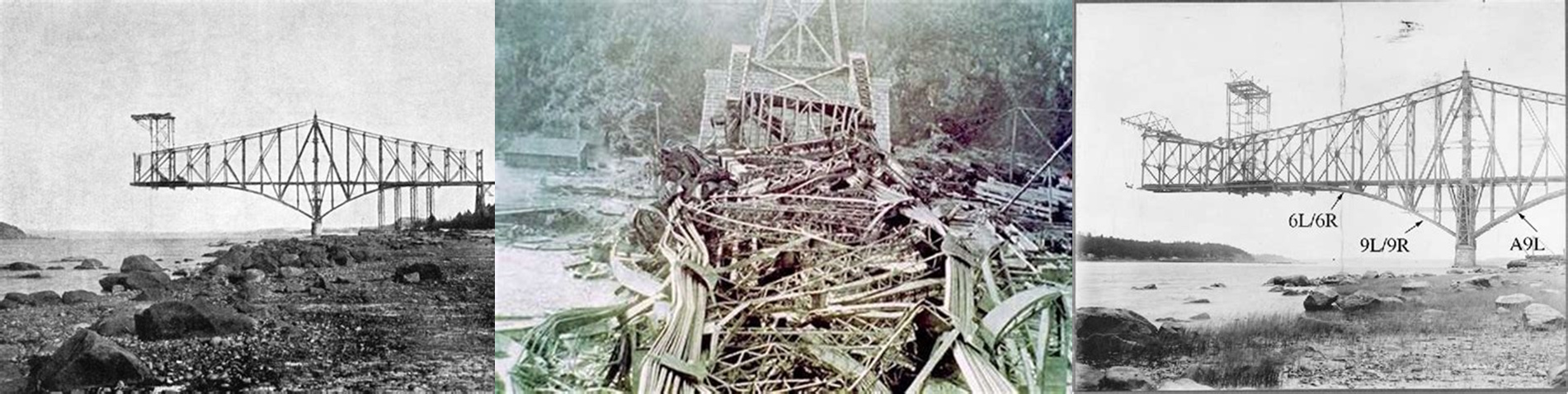
August 29, 1907, 5:30 PM. Workers on the Quebec Bridge watched in horror as the massive cantilever structure twisted and collapsed into the St. Lawrence River below. In just 15 seconds, Canada's worst bridge disaster claimed 75 lives and destroyed what was intended to be the world's longest cantilever span.
While the immediate cause involved compression member buckling, the disaster revealed fundamental flaws in connection design that would reshape engineering practice for the next century. The failure highlighted how individual bolts could perform perfectly according to their rated capacity, yet connections could still fail catastrophically when basic spacing and edge distance requirements were violated.
The Quebec Bridge tragedy demonstrated that bolt capacity alone tells only part of the connection story. The steel surrounding those bolts—the material that must transfer loads between connected elements—becomes the critical weak link when geometric constraints are ignored. Even the strongest bolts become useless when the supporting steel tears out beneath them.
P_bearing = 2.4 × d × t × F_u
This fundamental bearing capacity relationship governed early connection design, where d represents bolt diameter, t is the connected material thickness, and F_u denotes ultimate tensile strength. But this equation assumed adequate edge distances and bolt spacing—assumptions that proved deadly when violated.
The Engineering Foundation: Understanding the Geometry of Load Transfer
The Engineering Foundation: Understanding the Geometry of Load Transfer
Bolt spacing and edge distance requirements represent far more than arbitrary code provisions—they embody fundamental principles of load transfer mechanics that determine whether connections perform as ductile, predictable structural elements or fail in sudden, catastrophic modes that provide no warning of impending collapse.
The physics of load transfer in bolted connections involves complex stress concentrations around each bolt hole that create multiple potential failure paths through the connected material. When bolts are properly spaced, these stress fields develop independently, allowing each bolt to reach its full capacity. When spacing becomes inadequate, stress fields overlap and interact, creating failure mechanisms that no amount of bolt strength can prevent.
Modern connection design recognizes four distinct failure modes that must be evaluated independently: bolt shear, bolt bearing on connected material, tearout of connected material, and block shear failure. Each mode responds differently to geometric constraints, requiring systematic evaluation to identify the governing failure mechanism.
R_n = min[F_nv × A_b, 2.4 × d × t × F_u, U_bs × A_nt × F_u, 0.6 × F_u × A_nv + U_bs × F_u × A_nt]
This comprehensive capacity equation demonstrates how multiple failure modes compete, with the minimum value governing connection strength regardless of which mode controls. The systematic evaluation ensures that geometric constraints are properly considered in capacity calculations.
Edge distance requirements emerge from the need to develop adequate bearing stress distribution around bolt holes. When bolts are placed too close to material edges, bearing stresses concentrate over insufficient material areas, causing local crushing or tearout that prevents full bolt capacity development.
L_e,min = 2.0 × d_bolt
This minimum edge distance requirement ensures adequate material remains beyond the bolt centerline to develop bearing stresses without tearout failure. The relationship applies regardless of material thickness or bolt grade, reflecting the fundamental geometry of stress distribution around circular holes.
Bolt spacing requirements address the interaction between adjacent stress concentration zones. When bolts are spaced too closely, their individual stress fields overlap, creating combined stress states that exceed material capacity even when individual bolt stresses remain within acceptable limits.
s_min = 3.0 × d_bolt
The minimum spacing relationship ensures that stress concentrations around adjacent bolts develop independently, allowing each bolt to contribute its full capacity to connection strength without detrimental interaction effects.
Real-World Applications: Where Spacing Rules Shape Construction Practice
Real-World Applications: Where Spacing Rules Shape Construction Practice
Bolt spacing requirements profoundly influence everything from routine connection details to complex structural systems, dictating not only connection capacity but also fabrication costs, erection schedules, and architectural possibilities. Understanding these constraints enables engineers to optimize designs that balance structural performance with practical construction considerations.
High-rise construction presents particularly challenging spacing applications where connections must transfer enormous forces through limited geometric envelopes. Beam-to-column connections in moment frames often require dozens of bolts arranged in complex patterns that must satisfy spacing requirements while fitting within standard member dimensions and maintaining constructability.
Industrial construction demands connections capable of handling extreme loading conditions while accommodating the geometric constraints imposed by equipment layouts and access requirements. Heavy machinery foundations, crane runway connections, and process equipment supports all require careful attention to spacing rules to ensure adequate capacity while maintaining practical installation clearances.
Our repository's Bolt spacing and edge distances.xls calculation (downloaded over 1,200 times with a 3.9-star rating), developed by community contributors, addresses these complex design scenarios through systematic evaluation of all geometric constraints and failure modes that govern connection performance.
Bridge construction applications showcase the critical importance of spacing rules in long-span structures where connection failures can have catastrophic consequences. Splice connections in main load-carrying members often require hundreds of bolts arranged in patterns that must transfer massive forces while satisfying strict geometric requirements that ensure ductile failure modes.
Retrofit and strengthening projects frequently encounter existing structures with connections that violate modern spacing requirements. Historical construction often utilized closer bolt spacing that was acceptable under earlier design standards but inadequate by current criteria. Engineers must carefully evaluate these existing conditions and develop strengthening strategies that address geometric deficiencies.
Seismic design applications demand special attention to spacing requirements given the cyclic loading conditions that connections must survive. Earthquake forces subject bolted connections to repeated loading cycles that can cause fatigue failures at stress concentrations around bolt holes. Adequate spacing becomes essential for ensuring that connections maintain their capacity throughout multiple seismic events.
The Hidden Complexity: Why Distance Calculations Defeat Intuition
The Hidden Complexity: Why Distance Calculations Defeat Intuition
The deceptive simplicity of bolt spacing rules masks underlying complexity that challenges engineering intuition and demands rigorous analysis approaches. What appears as straightforward geometric relationships actually involves sophisticated interaction effects that can dramatically alter connection behavior in ways that simple distance measurements cannot capture.
Block shear failure represents one of the most complex spacing-related phenomena, involving simultaneous tension and shear failure along perpendicular planes that intersect at connection boundaries. This failure mode becomes critical when bolt groups are arranged near material edges, creating L-shaped or U-shaped failure paths that resist simple analysis.
R_n = 0.6 × F_u × A_nv + U_bs × F_u × A_nt ≤ 0.6 × F_y × A_gv + U_bs × F_u × A_nt
This block shear capacity equation demonstrates how tension and shear components combine along different failure planes, with net areas A_nv and A_nt calculated based on actual bolt hole locations and edge distances. The interaction creates capacity predictions that defy simple proportional relationships.
Stress concentration effects around bolt holes create localized stress amplifications that depend critically on hole quality, bolt fit, and loading direction. These concentrations can reach 3.0 times the nominal stress level, making material behavior around bolt holes fundamentally different from that predicted by average stress calculations.
While these equations look intimidating on paper, our XLC add-in displays them as easily readable mathematical equations directly in Excel, transforming the complex geometric relationships that govern bolt spacing into practical design tools that engineers can confidently apply without specialized training or expensive software.
Group action effects introduce nonlinear behavior that challenges traditional analysis approaches. As bolt groups develop capacity, individual bolts may reach yield before others, causing load redistribution that changes the effective spacing relationships throughout the loading process. This progressive yielding can lead to ductile overall behavior even when individual failure modes appear brittle.
C_f = Σ(x_i² + y_i²) / A_bolt
This flexibility coefficient demonstrates how bolt group geometry affects load distribution, with individual bolt coordinates x_i and y_i determining how loads share among group members. The relationship shows why seemingly minor spacing changes can dramatically affect connection behavior.
Manufacturing tolerances add another layer of complexity that defies simple geometric analysis. Standard bolt holes are typically 1/16" larger than bolt diameters, creating initial clearances that affect load transfer mechanisms and stress distributions. These seemingly minor dimensional variations can alter failure modes and capacity predictions in ways that require careful consideration during design.
Connection flexibility introduces dynamic considerations that static spacing calculations cannot capture. Bolted connections exhibit complex load-deformation behavior that depends on bolt pretension, surface conditions, and loading history. This flexibility affects structural response in ways that extend far beyond simple connection capacity calculations.
Professional Approach: Ensuring Spacing Rule Compliance and Optimization
Professional Approach: Ensuring Spacing Rule Compliance and Optimization
The critical nature of bolt spacing requirements demands systematic professional practices that extend beyond simple rule compliance to encompass optimization strategies, quality assurance procedures, and risk management approaches that ensure reliable connection performance throughout the structure's design life.
The ExcelCalcs community shares a passion for making accurate calculations with MS Excel, providing a platform where engineers can access expert knowledge through our comments feature and benefit from collective experience with spacing optimization across diverse structural applications and connection types.
Professional spacing analysis begins with comprehensive failure mode evaluation that considers all potential mechanisms simultaneously rather than checking each requirement in isolation. Modern design approaches recognize that spacing rules interact in complex ways that require systematic evaluation to identify the true governing constraints.
Optimization strategies seek to balance structural efficiency with practical construction considerations. Minimum spacing requirements often conflict with architectural constraints, member sizes, and fabrication capabilities, requiring engineering judgment to develop solutions that satisfy all competing demands while maintaining adequate safety margins.
Our repository's worked solutions give engineers a head start in developing systematic spacing evaluation procedures while building on existing Excel skills with a much faster learning curve than specialized connection design software that can cost thousands of dollars annually and require extensive training programs.
Quality control verification becomes essential given the numerous geometric constraints and their complex interactions. Field inspection procedures must verify not only that spacing requirements are met but also that fabrication tolerances and erection practices maintain the assumptions inherent in spacing calculations. Small deviations from design dimensions can have major impacts on connection capacity.
Documentation standards require clear presentation of spacing calculations and their underlying assumptions. Connection details must communicate spacing requirements to fabricators and erectors while providing sufficient information for field verification. Quality assurance through comments feature and peer review helps identify potential misinterpretations before they become field problems.
Risk assessment procedures consider the consequences of spacing violations and develop appropriate response strategies. Critical connections may warrant enhanced spacing requirements or additional redundancy, while routine connections might accept standard provisions with confidence in their adequacy for the intended application.
Repository Showcase: Comprehensive Bolt and Connection Design Solutions
Repository Showcase: Comprehensive Bolt and Connection Design Solutions
Beyond our flagship bolt spacing analysis, engineers can access specialized calculations including BOLTGRP.xls (1,320 downloads, 4.6-star rating), SimpleBoltCalc.xls (1,302 downloads, 3.9-star rating), and Ultimate shear capacity of bolt group.xls for complex loading scenarios (719 downloads, 5.0-star rating).
For specialized applications, our repository includes BoltedJoint.xls (863 downloads, 4.4-star rating), Thread Stripping.xls for threaded connection analysis (740 downloads, 4.4-star rating), and Quick and Dirty Bolt Sizing Calculation.xls (678 downloads, 4.4-star rating). International practitioners can utilize Capacities of Bolts and Welds to BS449: Part 2 for British standards (380 downloads, 4.8-star rating), while advanced applications can access Tables for strength of bolted joints in thin coldformed steel sheets to AS4600 designed for Australian specifications (149 downloads, 4.4-star rating). This diversity ensures that regardless of your local code requirements or specific connection challenges, our community has developed comprehensive solutions to meet your engineering needs.
Specialized failure mode analysis tools include TNT_Tear-Out for tearout evaluation (200 downloads, 4.0-star rating), PRYING9.xls for prying action analysis (640 downloads, 4.5-star rating), and Bolt torque/tension calc for installation verification (295 downloads, 3.8-star rating). The comprehensive nature of our bolt design library reflects decades of collective engineering experience with both traditional methods and modern limit states approaches.
Start Your Bolt Spacing Design Journey Today
Start Your Bolt Spacing Design Journey Today
The complexity of modern bolt spacing requirements demands calculation tools that incorporate all geometric constraints and failure modes while remaining accessible to practicing engineers. Our Bolt spacing and edge distances.xls calculation represents the culmination of extensive community development, incorporating all spacing requirements and failure mechanisms into a comprehensive design tool that handles the geometric complexity of modern connection analysis.
We extend our appreciation to the engineering contributors who developed these essential calculation tools, transforming the theoretical requirements of spacing provisions into practical design solutions that serve engineers worldwide. Their expertise has created calculation templates that continue to evolve with code updates and incorporate lessons learned from both successful projects and documented connection failures.
Join the ExcelCalcs community with a $99 professional subscription—insignificant compared to MathCAD, Mathematica, or Maple—and gain access to our complete repository of bolt and connection design solutions. Students and educators benefit from our 50% academic discount, while free trials allow you to explore the comprehensive capabilities of our spacing calculation tools without commitment.
Join the ExcelCalcs community today and discover why thousands of engineers trust our templates for their most critical connection design challenges. Because when bolts must transfer loads reliably through steel connections, you need calculations that understand why distance truly matters in structural engineering.