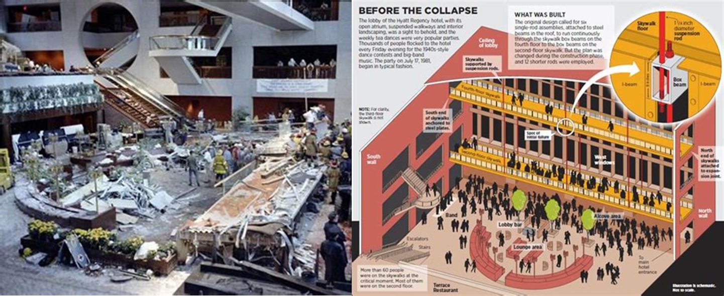
July 17, 1981, 7:05 PM. The grand atrium of Kansas City's Hyatt Regency Hotel filled with music and dancing as over 1,600 guests celebrated at a tea dance. Above them, suspended walkways spanned the four-story space in an architectural triumph of steel and concrete. In seconds, that triumph became America's deadliest structural engineering disaster.
The catastrophic failure claimed 114 lives and injured over 200 when the fourth-floor walkway's hanger rod connections failed, sending both the fourth and second-floor walkways crashing down. While the immediate cause involved a fateful design change in the hanger rod connections, the disaster highlighted a fundamental weakness in how engineers understood and designed anchorage to concrete.
The failure exposed how seemingly robust connections could collapse when subjected to forces that challenged basic assumptions about concrete behavior. At its core, the tragedy demonstrated the critical importance of understanding how concentrated loads transfer from steel elements into concrete through anchorage systems.
T_ultimate = A_bolt × f_uta
This simple relationship—ultimate tension equals bolt area times ultimate tensile strength—governed engineering practice for decades. But the Hyatt Regency collapse revealed that bolt strength alone tells only part of the story. The concrete foundation itself could fail catastrophically before the bolt reached its capacity.
The Engineering Foundation: Understanding Concrete Anchorage Revolution
The Engineering Foundation: Understanding Concrete Anchorage Revolution
The development of ACI 318 Appendix D represents one of the most significant advances in structural engineering of the past quarter-century. This revolutionary approach fundamentally changed how engineers analyze anchorage to concrete, moving beyond simple bolt calculations to comprehensive evaluation of concrete failure mechanisms that earlier methods completely ignored.
Traditional anchorage design relied on empirical formulas developed through limited testing of specific configurations. Engineers calculated allowable loads based on bolt strength and arbitrary safety factors, with little consideration for how loads actually transferred from steel anchors into the surrounding concrete matrix. This approach worked adequately for routine applications but failed catastrophically when subjected to unusual loading conditions or geometric constraints.
Appendix D introduced a rational design methodology based on the concrete capacity design (CCD) method, developed through extensive research at the University of Stuttgart. This approach recognizes that anchor failures occur through multiple potential mechanisms, each governed by distinct physical principles that must be evaluated independently.
N_concrete = k × √(f'_c) × A_concrete × Ψ_factors
This fundamental relationship governs concrete breakout capacity, where k represents a geometry factor, f'_c is the concrete compressive strength, A_concrete defines the projected failure area, and Ψ_factors account for various modification conditions including edge effects, cracking, and supplementary reinforcement.
The projected area concept revolutionized anchorage analysis by recognizing that concrete failure occurs along predictable geometric surfaces. For tension loading, concrete breaks out in a roughly pyramidal shape extending from the anchor to the concrete surface, with the failure area directly proportional to the embedment depth.
A_Nc = 9 × h_ef²
Where A_Nc represents the projected concrete failure area and h_ef is the effective embedment depth. This simple geometric relationship provides the foundation for calculating concrete breakout capacity, replacing arbitrary formulas with physics-based analysis.
Appendix D also introduced the critical concept of interaction effects between multiple anchors. When anchors are spaced closely, their individual failure cones overlap, reducing the effective concrete area available to resist loads. This interaction dramatically affects capacity calculations and explains many historical failures in anchor groups.
A_Nc,group = A_Nc,single × N_anchors × Ψ_overlap
The overlap modification factor Ψ_overlap accounts for the reduction in capacity when failure surfaces intersect, ensuring that group effects are properly considered in design calculations.
Real-World Applications: Where Appendix D Transforms Modern Construction
Real-World Applications: Where Appendix D Transforms Modern Construction
The impact of Appendix D extends far beyond academic theory, fundamentally changing how engineers approach anchorage design in everything from routine construction details to critical infrastructure projects. Its rational methodology has enabled safer, more economical designs while providing the analytical tools necessary for complex retrofitting and strengthening applications.
Seismic design represents perhaps the most demanding application of Appendix D principles. Earthquake loading subjects anchor bolts to cyclic tension and shear forces that can exceed static design loads by significant margins. The methodology's ability to account for concrete cracking, edge effects, and supplementary reinforcement provides the design confidence necessary for critical seismic applications.
Industrial construction relies heavily on Appendix D for equipment anchorage applications where dynamic loading, vibration, and extreme operating conditions challenge traditional design approaches. Heavy machinery foundations, pressure vessel supports, and crane rail connections all benefit from the methodology's comprehensive failure mode evaluation and explicit treatment of concrete behavior under concentrated loads.
Our repository's Appendix D - Anchor Bolt Anchorage ACI 318 calculation (downloaded over 1,427 times with a 4.5-star rating), developed by community contributors, addresses these complex design scenarios through comprehensive analysis of all potential failure modes including concrete breakout, pullout, side-face blowout, and steel failure.
Retrofit and strengthening projects have particularly benefited from Appendix D's explicit treatment of edge effects and concrete condition factors. Existing structures often require anchor installation near edges or in degraded concrete where traditional methods provide inadequate guidance. The methodology's systematic approach to these challenging conditions has enabled countless successful strengthening projects.
Bridge construction applications demand anchor systems capable of transferring massive loads from superstructure elements to substructure components. Bearing anchorage, expansion joint details, and seismic isolation systems all rely on Appendix D methodology to ensure adequate capacity while optimizing material usage through rational design approaches.
Post-installed anchoring systems have revolutionized construction practices, enabling secure connections in existing concrete structures that were impossible with traditional cast-in-place methods. Chemical anchors, expansion anchors, and undercut anchors all require the sophisticated analysis capabilities that Appendix D provides for reliable performance evaluation.
The Hidden Complexity: Why Bolt Strength Calculations Miss the Point
The Hidden Complexity: Why Bolt Strength Calculations Miss the Point
The elegance of Appendix D lies in its recognition that anchor bolt failures rarely occur where engineers expect them. While traditional methods focused exclusively on bolt tensile strength, real-world failures typically involve complex concrete mechanisms that earlier approaches completely ignored.
Concrete breakout represents the most common failure mode in tension applications, yet its analysis requires consideration of factors that seem unrelated to the anchor itself. Edge distances, concrete cracking patterns, and the presence of reinforcing steel all dramatically affect capacity through mechanisms that simple bolt calculations cannot capture.
Ψ_ec,N = (1 + 2 × e_N') / (3 × h_ef) ≤ 1.0
This edge effect modification factor demonstrates how proximity to concrete edges reduces breakout capacity in ways that have no relationship to bolt properties. The factor can reduce capacity by 50% or more for anchors near structural edges, a critical consideration completely absent from traditional design approaches.
Supplementary reinforcement effects add another layer of complexity that defies simple analysis. When adequate reinforcement surrounds an anchor group, failure modes can shift from brittle concrete breakout to ductile steel yielding, fundamentally changing both capacity and behavior characteristics.
While these equations look intimidating on paper, our XLC add-in displays them as easily readable mathematical equations directly in Excel, transforming the complex theoretical relationships of Appendix D into practical design tools that engineers can confidently apply without requiring specialized software or extensive training.
The interaction between different failure modes creates analysis challenges that demand systematic evaluation approaches. A single anchor group must be checked for concrete breakout in tension, concrete pryout in shear, steel failure of the anchor, pullout from concrete, side-face blowout, and concrete crushing—with the governing mode determining design capacity.
φ_N_n = φ × min[N_sa, N_cb, N_p, N_sb]
This relationship demonstrates how multiple failure modes must be evaluated, with the minimum value governing design capacity regardless of which mode controls. The systematic evaluation of all potential failure mechanisms ensures that the weakest link is identified and properly addressed.
Construction effects introduce additional variables that challenge theoretical predictions. Concrete placement conditions, curing environment, and installation tolerances all affect anchor performance in ways that require engineering judgment beyond prescriptive calculations. The methodology provides frameworks for addressing these real-world considerations while maintaining design reliability.
Professional Approach: Ensuring Appendix D Implementation Excellence
Professional Approach: Ensuring Appendix D Implementation Excellence
The complexity of Appendix D methodology demands rigorous professional practices that extend far beyond simple calculation accuracy. Successful implementation requires understanding the theoretical foundations, recognizing the limitations of the approach, and maintaining quality assurance standards that ensure reliable performance across diverse applications.
The ExcelCalcs community shares a passion for making accurate calculations with MS Excel, providing a platform where engineers can access expert knowledge through our comments feature and benefit from collective experience with Appendix D applications across multiple industries and project types.
Professional implementation begins with proper categorization of anchor types and loading conditions. Post-installed anchors, cast-in-place anchors, and headed studs all exhibit different behavioral characteristics that affect which portions of Appendix D apply. Misclassification of anchor type or loading conditions can lead to unconservative designs with potentially dangerous consequences.
Quality control verification becomes critical given the numerous factors and modification coefficients involved in Appendix D calculations. Our repository's worked solutions give engineers a head start in developing systematic checking procedures while building on existing Excel skills with a much faster learning curve than specialized anchorage design software that costs thousands of dollars annually.
The methodology requires careful consideration of concrete condition factors that reflect real-world installation environments. Cracked versus uncracked concrete assumptions can affect capacity by 25% or more, making accurate assessment of structural conditions essential for reliable design. Professional engineers must develop judgment regarding when concrete cracking should be assumed based on structural loading and environmental conditions.
Field inspection and quality assurance procedures must align with the assumptions inherent in Appendix D calculations. Installation tolerances, concrete quality verification, and anchor testing requirements all affect whether design assumptions remain valid during construction. Quality assurance through comments feature and peer review helps identify potential disconnects between design assumptions and field conditions.
Repository Showcase: Comprehensive Anchorage Design Solutions
Repository Showcase: Comprehensive Anchorage Design Solutions
Beyond our flagship Appendix D - ACI 318 analysis, engineers can access specialized calculations including Appendix D - Anchor Bolt Anchorage (1,295 downloads, 4.3-star rating), BASEPLT9.xls (1,963 downloads, 4.3-star rating), and Anchor Bolt anchorage for general applications (803 downloads, 4.2-star rating).
For specialized applications, our repository includes Design of Anchor Plates (314 downloads, 4.7-star rating), Anchor Reinforcement for supplementary steel design (955 downloads, 4.3-star rating), and Anchor Reinforcement Metric Version (307 downloads, 4.1-star rating). Geotechnical practitioners can utilize Bored Piles Wall and Ground Anchors for earth retention systems (743 downloads, 4.4-star rating), while specialized structural applications can access Analysis of Sheet Pile Wall - Cantilevered and Anchored (432 downloads, 4.4-star rating). This diversity ensures that regardless of your specific anchorage application or local design requirements, our community has developed comprehensive solutions to meet your engineering needs.
Advanced bolt and connection analysis tools include BOLTGRP.xls for complex loading patterns (1,320 downloads, 4.6-star rating), Ultimate shear capacity of bolt group.xls (719 downloads, 5.0-star rating), and PRYING9.xls for prying action analysis (640 downloads, 4.5-star rating). The comprehensive nature of our anchorage library reflects decades of collective engineering experience with both traditional methods and modern Appendix D approaches.
Start Your Appendix D Design Journey Today
Start Your Appendix D Design Journey Today
The sophistication of modern anchorage design demands calculation tools that incorporate the latest advances in concrete behavior understanding while remaining accessible to practicing engineers. Our Appendix D - Anchor Bolt Anchorage ACI 318 calculation represents the culmination of extensive community development, incorporating all failure modes and modification factors into a comprehensive design tool that handles the complexity of modern anchorage analysis.
We extend our appreciation to the engineering contributors who developed these essential calculation tools, transforming the theoretical advances of Appendix D methodology into practical design solutions that serve engineers worldwide. Their expertise has created calculation templates that continue to evolve with code updates and incorporate lessons learned from both successful projects and documented failures.
Join the ExcelCalcs community with a $99 professional subscription—insignificant compared to MathCAD, Mathematica, or Maple—and gain access to our complete repository of anchorage design solutions. Students and educators benefit from our 50% academic discount, while free trials allow you to explore the comprehensive capabilities of our Appendix D calculation tools without commitment.
Join the ExcelCalcs community today and discover why thousands of engineers trust our templates for their most critical anchorage design challenges. Because when connections must transfer loads safely from steel to concrete, you need calculations that understand the revolution in anchorage engineering.