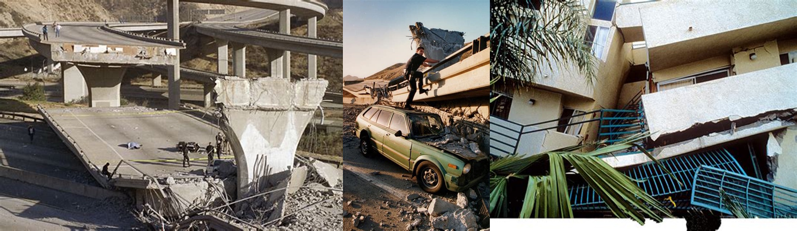
January 17, 1994, 4:30 AM. Los Angeles slept as the earth beneath unleashed one of the most devastating lessons in structural engineering history. The magnitude 6.7 Northridge earthquake didn't just wake a city—it shattered fundamental assumptions about steel moment-resisting frame connections that had stood unchallenged for decades.
Within minutes, over 200 welded beam-to-column connections failed in supposedly "ductile" steel moment frames. Buildings designed to bend without breaking instead suffered brittle fractures at their most critical joints. The economic toll exceeded $20 billion, but the engineering revelation was priceless: our understanding of moment transfer in steel connections was fundamentally flawed.
At the heart of this catastrophe lay a deceptively simple engineering relationship that governs all moment connections:
M_applied = F_tension × d_arm
Where the applied moment equals the tension force times the lever arm distance. When this elegant equilibrium fails, as it did that morning in Northridge, buildings don't just bend—they break.
The Engineering Foundation: Understanding Moment Transfer Magic
The Engineering Foundation: Understanding Moment Transfer Magic
Steel connections are the unsung heroes of structural engineering, quietly transferring enormous forces between members with mathematical precision. End plate connections represent one of the most sophisticated approaches to this challenge, creating moment-resisting joints through carefully orchestrated tension and compression forces.
The fundamental principle governing end plate behavior centers on the concept of force couples—pairs of equal and opposite forces separated by a distance that create pure moment. In an end plate connection, this manifests as tension in the upper bolt rows balanced by compression in the lower portion of the connection.
M_ultimate = T_bolt × (d_bolt - d_compression)
Where M_ultimate represents the maximum transferable moment, T_bolt is the bolt tension capacity, and the parenthetical term defines the effective lever arm between tension and compression centers.
The beauty of end plate connections lies in their ability to develop the full plastic moment capacity of the connected beam through controlled yielding mechanisms. Unlike welded connections that can fail brittlely, properly designed end plates achieve ductility through sequential yielding of the plate, bolts, or beam components.
φ_M_n = φ × Z_x × F_y
This relationship defines the design moment capacity, where φ represents the resistance factor, Z_x is the plastic section modulus, and F_y denotes the yield strength. The connection must transfer this full beam capacity to maintain structural integrity.
The critical design challenge involves managing prying action—the tendency of the end plate to curl under load, creating additional tension forces in the bolts beyond those calculated from simple force equilibrium. This phenomenon dramatically affects bolt performance and requires sophisticated analysis.
Q = (T_bolt × t_plate²) / (27 × δ × F_y)
Where Q represents the prying force amplification factor, t_plate is the plate thickness, δ is the bolt spacing parameter, and F_y is the plate yield strength. This relationship demonstrates why plate thickness selection cannot rely on simple strength calculations alone.
Real-World Applications: Where End Plates Shape Our Built Environment
Real-World Applications: Where End Plates Shape Our Built Environment
End plate moment connections form the backbone of modern steel construction, providing the rigidity necessary for everything from high-rise office buildings to industrial manufacturing facilities. Their ability to transfer moments while maintaining constructability makes them indispensable in contemporary structural engineering.
In high-rise construction, end plate connections enable the continuous moment frames that resist wind and seismic forces. These connections must transfer moments exceeding 500 kip-feet while accommodating the thermal movements and construction tolerances inherent in tall building construction. The standardized bolt patterns and shop-welded plates significantly reduce field erection time compared to fully welded alternatives.
Industrial applications demand end plate connections capable of handling dynamic loading from heavy machinery, crane operations, and process equipment. Manufacturing facilities often require clear spans exceeding 60 feet with minimal deflection criteria, necessitating rigid moment connections that can transfer substantial forces without compromising structural performance.
Our repository's ENDPLMC9.xls calculation (downloaded over 1,042 times with a 4.5-star rating), developed by community contributors, addresses these complex design scenarios through comprehensive analysis of plate bending, bolt tension, and prying action effects.
Seismic design applications represent perhaps the most demanding use of end plate connections. Following the Northridge earthquake, engineers developed enhanced end plate details specifically for seismic regions, featuring thicker plates, larger bolts, and extended stiffeners to ensure ductile behavior under cyclic loading. These connections must demonstrate the ability to undergo multiple yield cycles without degradation.
Bridge construction utilizes end plate connections for continuity over piers and in segmental construction applications. The connections must resist both positive and negative moments while accommodating the temperature-induced movements typical in long-span structures. Fatigue considerations become paramount given the millions of load cycles these connections experience over their design life.
The Hidden Complexity: Why Simple Plates Become Engineering Puzzles
The Hidden Complexity: Why Simple Plates Become Engineering Puzzles
What appears as a straightforward steel plate with bolt holes conceals layers of complex engineering behavior that challenge even experienced structural engineers. The interaction between plate bending, bolt tensioning, and connection geometry creates a web of interdependent variables that resist simple analysis approaches.
Prying action represents the most significant complication in end plate design. As loads increase, the plate deforms into a curved shape, moving the bolt force application point away from the plate centerline. This geometric change amplifies bolt tensions far beyond values calculated from simple equilibrium, potentially causing unexpected failures.
T_total = T_applied + Q_prying = T_applied × (1 + α × β)
Where α represents the plate flexibility factor and β accounts for bolt stiffness effects. The prying amplification can increase bolt forces by 50% or more, making accurate prediction essential for safe design.
Material property variations add another layer of complexity. Steel plates exhibit different yield strengths in rolling versus transverse directions, while bolt properties vary significantly between manufacturers. Temperature effects can alter material properties by 20% or more, particularly important in industrial applications with extreme operating conditions.
While these equations look intimidating on paper, our XLC add-in displays them as easily readable mathematical equations directly in Excel, transforming complex theoretical relationships into practical design tools that engineers can confidently apply in real-world situations.
Connection flexibility introduces dynamic considerations often overlooked in preliminary design. End plate connections exhibit semi-rigid behavior, with connection stiffness falling between fully pinned and fully fixed assumptions. This flexibility affects building periods, deflections, and force distributions throughout the structural system.
K_connection = (M_service) / (θ_rotation)
This rotational stiffness relationship governs how moments distribute between beams and columns, influencing the entire structural analysis. Ignoring connection flexibility can lead to unconservative designs that fail to account for actual structural behavior.
Fabrication and erection tolerances create additional challenges. Bolt hole alignment, plate out-of-flatness, and member length variations all affect connection performance. Modern design approaches incorporate these real-world imperfections through statistical analysis and probabilistic design methods that ensure reliability despite manufacturing uncertainties.
Professional Approach: Ensuring End Plate Connection Reliability
Professional Approach: Ensuring End Plate Connection Reliability
The complexity of end plate connections demands a systematic engineering approach that balances theoretical understanding with practical construction considerations. Professional design practices emphasize multiple failure mode evaluation, comprehensive documentation, and rigorous quality assurance procedures that protect both public safety and design liability.
The ExcelCalcs community shares a passion for making accurate calculations with MS Excel, providing a platform where engineers can access expert knowledge through our comments feature and collaborative peer review process. This community-driven approach ensures that calculation methods evolve with industry best practices and incorporate lessons learned from both successful projects and documented failures.
Modern end plate design requires checking numerous potential failure modes: bolt tension and shear, plate yielding in flexure, bolt bearing on plates, block shear in plates, weld capacity, and beam web yielding. Each mode must be evaluated independently, with the governing case determining the connection capacity. Professional engineers understand that connection safety depends on the weakest link, not the strongest component.
Quality assurance protocols demand independent verification of all calculations, particularly for critical connections in high-consequence structures. Our repository's worked solutions give engineers a head start in developing comprehensive analysis procedures while building on existing Excel skills with a much faster learning curve than specialized software alternatives.
Code compliance verification presents ongoing challenges as design standards evolve. The AISC 360 specification undergoes regular updates that affect connection design requirements, while regional building codes may impose additional constraints. Professional practice requires staying current with these changes and understanding their implications for both new construction and existing building evaluation.
Documentation standards have become increasingly important following litigation trends in the construction industry. Engineers must demonstrate not only that connections meet code requirements but also that appropriate safety factors and design assumptions were applied. Quality assurance through comments feature and peer review helps identify potential issues before they become field problems.
Repository Showcase: Comprehensive Steel Connection Solutions
Repository Showcase: Comprehensive Steel Connection Solutions
Beyond our flagship ENDPLMC9 analysis, engineers can access specialized calculations including BASEPLT9.xls (1,963 downloads, 4.3-star rating), gowelding.com Weld Calculations (1,567 downloads, 4.5-star rating), and Ultimate shear capacity of bolt group.xls for complex loading scenarios (719 downloads, 5.0-star rating).
For specialized applications, our repository includes Static load capacity of the parallel loaded fillet welds.xls (468 downloads, 4.0-star rating), Static load capacity of the transverse-loaded fillet welds.xls for welded connections (333 downloads, 4.7-star rating), and Weld line assessment - 2 horizontal welds.xls (400 downloads, 4.4-star rating). International practitioners can utilize Tables for strength of bolted joints in thin coldformed steel sheets to AS4600 for Australian standards, while North American engineers can access AISC360 05 LRFD Shear Plate bolted connection calculations designed for modern specifications. This diversity ensures that regardless of your local code requirements or specific design challenges, our community has developed solutions to meet your needs.
Advanced connection analysis tools include Taki FE Spreadsheet 02 - bolted_joint_070506.xls for finite element verification (395 downloads, 3.0-star rating), while fabrication support comes through Weld line assessment - 2 vertical welds.xls (294 downloads, 4.0-star rating) for quality control verification. The comprehensive nature of our connection library reflects decades of collective engineering experience distilled into practical calculation tools.
Start Your Connection Design Journey Today
Start Your Connection Design Journey Today
The sophistication of modern steel connections demands tools that match their complexity, yet remain accessible to practicing engineers. Our ENDPLMC9.xls calculation represents the culmination of extensive community development, incorporating industry best practices into a comprehensive design tool that handles prying action, plate yielding, and bolt capacity evaluation with professional-grade accuracy.
We extend our appreciation to the engineering contributors who developed these essential calculation tools, transforming complex theoretical relationships into practical design solutions that serve thousands of engineers worldwide. Their expertise has created a repository that continues to evolve with industry advances and lessons learned from real-world applications.
Join the ExcelCalcs community with a $99 professional subscription—insignificant compared to MathCAD, Mathematica, or Maple—and gain access to our complete repository of connection design solutions. Students and educators benefit from our 50% academic discount, while free trials allow you to explore our calculation capabilities without commitment.
Join the ExcelCalcs community today and discover why thousands of engineers trust our templates for their most critical connection design challenges. Because when moments must transfer and connections must perform, you need calculations that understand the art of structural engineering.