When Microscopic Flaws Become Macroscopic Disasters: The Silver Bridge Tragedy
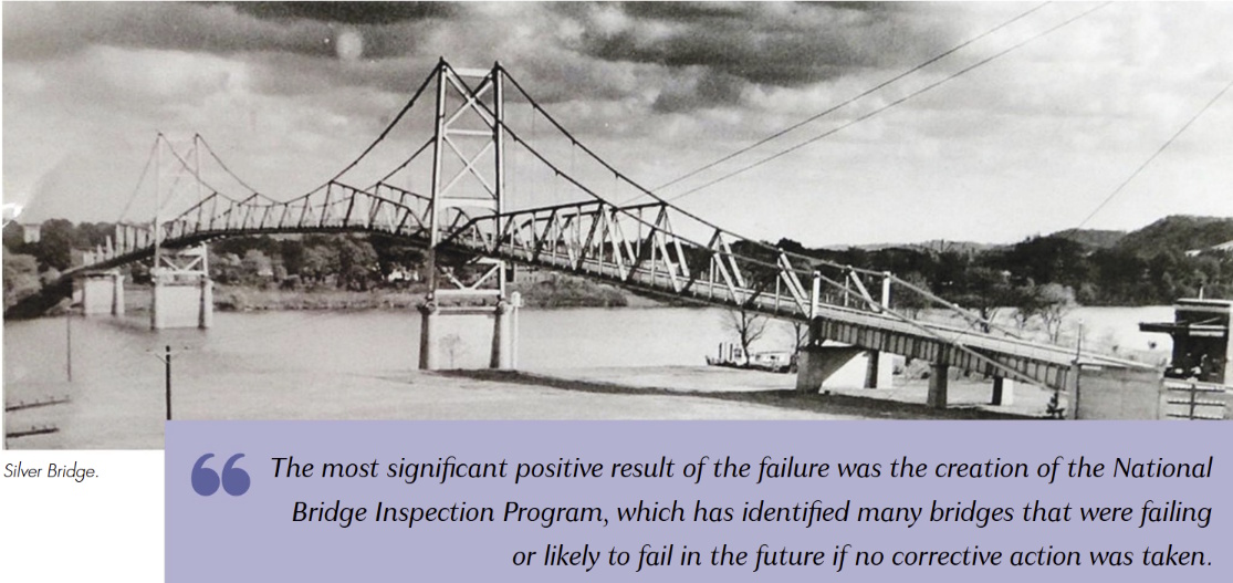
At 5:00 PM on December 15, 1967, Christmas shoppers crowded the Silver Bridge connecting Point Pleasant, West Virginia, to Gallipolis, Ohio, when the structure suddenly collapsed into the Ohio River. The catastrophic failure killed 46 people and injured 9 others, sending 31 vehicles plummeting into the icy waters below. The cause was traced to a microscopic crack - just 0.1 inches deep - in a single eye-bar that had developed over the bridge's 40-year lifespan.
The disaster revealed the critical importance of understanding material science and fabrication quality in structural connections. The eye-bar that failed had been manufactured using 1920s steel production methods that created internal stress concentrations and material inconsistencies. A small flaw in the steel, likely introduced during the original casting and welding processes, grew steadily through stress corrosion and corrosion fatigue until it reached critical size and triggered brittle fracture.
The fundamental engineering principle that failed was the assumption of material homogeneity and perfection:
Actual_strength = Design_strength × Quality_factor × Time_degradation
Where actual strength depends on manufacturing quality and long-term environmental effects that theoretical calculations often ignore. The Silver Bridge disaster demonstrated that even minor fabrication defects, including welding flaws, can propagate over decades to cause catastrophic failure in critical structural elements.
The Engineering Foundation: Understanding Welding Metallurgy
Welding represents one of the most complex materials science processes in structural engineering, involving rapid heating, melting, solidification, and cooling that create localized changes in material properties, residual stresses, and potential defect formation. Unlike mechanical fasteners that join materials without altering their fundamental properties, welding creates new metallurgical structures with characteristics that depend heavily on welding parameters, materials, and quality control.
The fundamental science behind welding begins with the heat-affected zone (HAZ), the region adjacent to the weld where base metal experiences thermal cycles that alter its microstructure without melting. The HAZ often exhibits different mechanical properties than either the base metal or weld metal, creating a complex stress distribution in welded joints:
Heat_input = (Voltage × Current × 60) / (1000 × Travel_speed)
Cooling_rate = k × (T_initial - T_ambient) / t^0.5
HAZ_width = C × √(Heat_input / Thickness)
Where heat input controls weld penetration and HAZ formation, cooling rate affects microstructure development, T_initial and T_ambient are initial and ambient temperatures, t is time, k is a thermal constant, and C is a material-dependent coefficient.
The metallurgical transformations during welding create multiple zones with distinct properties. The fusion zone contains solidified weld metal with a cast structure different from the wrought base material. The HAZ includes regions of grain growth, phase transformation, and tempering that can either strengthen or weaken the joint depending on base material chemistry and thermal history.
Residual stresses develop during welding due to non-uniform heating and cooling, creating locked-in stress patterns that can reach yield strength magnitude. These residual stresses interact with applied loads to determine actual stress levels in service:
σ_total = σ_applied + σ_residual + σ_thermal
σ_residual = E × α × ΔT × Constraint_factor
Where σ_total is total stress, σ_applied is applied stress, σ_residual represents residual stress, σ_thermal accounts for thermal effects, E is elastic modulus, α is coefficient of thermal expansion, ΔT is temperature change, and Constraint_factor depends on joint geometry.
The physical meaning behind welding science extends beyond simple joining to encompass the creation of new material systems with properties that must be controlled through proper procedure selection, parameter control, and quality assurance. Understanding these metallurgical principles becomes essential for reliable joint performance under service conditions.
Real-World Applications: Where Welding Defines Structural Integrity
Welding applications span every major construction sector, from building frames and bridges to pressure vessels and offshore platforms. The quality and reliability of welded joints often determine the safety and serviceability of entire structural systems, making welding analysis and design critical engineering functions.
Structural steel construction relies heavily on welded connections for moment-resisting frames, where beam-to-column joints must develop full member capacity while providing adequate ductility for seismic loading. The Northridge earthquake revealed the importance of proper welding procedures and quality control, leading to major revisions in welding specifications and inspection requirements. Our repository's gowelding.com Weld Calculations (1,567 downloads, 4.5-star rating), developed by community contributor Brian Holcomb, provides comprehensive analysis tools for evaluating weld capacity under various loading conditions.
Pressure vessel construction demands exceptional weld quality due to the consequences of failure and the complex stress states in cylindrical and spherical shells. Welding procedures for pressure vessels require qualification testing, radiographic inspection, and compliance with codes such as ASME Section VIII that specify detailed requirements for materials, procedures, and quality control. Our repository's WELDGRP.xls calculation (803 downloads, 4.6-star rating) offers sophisticated analysis capabilities for weld group behavior under combined loading.
Offshore construction presents unique welding challenges due to harsh environmental conditions, fatigue loading from waves, and limited access for inspection and maintenance. Underwater welding techniques enable repairs without dry-docking structures, but require specialized procedures and quality control measures to ensure reliable performance. Fatigue resistance becomes a primary design consideration for offshore welded joints subject to millions of load cycles over their service life.
Heavy industrial construction frequently involves field welding of large sections where quality control becomes particularly challenging. Multi-pass welding procedures for thick sections require careful attention to interpass temperature, preheat requirements, and post-weld heat treatment to achieve desired mechanical properties. Our repository's Analysis & Design of Weld Groups (754 downloads, 4.3-star rating) provides detailed analysis methods for complex weld patterns subjected to multiple load components.
The Hidden Complexity: Why Perfect Welds Remain Elusive
The apparent simplicity of welding - melting materials together to create continuous joints - conceals extraordinary complexity that makes perfect welds virtually impossible to achieve consistently. The primary complicating factors involve metallurgical transformations, thermal stresses, chemical interactions, and human factors that resist complete theoretical prediction or control.
Metallurgical complexity arises from the rapid heating and cooling cycles that create non-equilibrium microstructures with properties different from those predicted by equilibrium phase diagrams. Solidification defects such as porosity, inclusions, and segregation can form depending on welding parameters, shielding gas composition, and base material cleanliness. The heat-affected zone experiences thermal cycles that may create hard, brittle zones or soft, weak zones depending on base material composition and cooling rate.
Chemical interactions between filler metal, base material, and atmospheric contaminants create additional variables affecting weld quality. Hydrogen pickup from moisture or organic contaminants can cause delayed cracking hours or days after welding. Sulfur and phosphorus in base materials can cause hot cracking during solidification. Carbon migration between weld metal and base material can alter mechanical properties in unexpected ways.
The mathematical complexity becomes apparent when considering the full range of variables affecting weld performance:
Weld_strength = f(chemistry, heat_input, cooling_rate, restraint, defects)
Fatigue_life = C / (Δσ_eff × Geometry_factor × Environment_factor)^m
Crack_growth = A × (ΔK)^n × Environment_acceleration
Where Weld_strength depends on multiple interacting variables, Δσ_eff is effective stress range, C, A, m, and n are material constants, ΔK is stress intensity factor range, and various factors account for geometry, environment, and defect effects.
While these equations look intimidating on paper, our XLC add-in displays them as easily readable mathematical equations directly in Excel, enabling engineers to perform comprehensive weld analyses while maintaining the documentation and verification capabilities essential for code compliance and quality assurance.
Human factors introduce another layer of complexity that can dramatically affect weld quality. Welder skill, training, and certification directly impact defect rates and mechanical properties. Welding position, accessibility, and environmental conditions influence the ability to maintain proper procedures. Equipment maintenance, calibration, and setup affect heat input consistency and shielding effectiveness.
Quality control variations represent perhaps the greatest challenge in welding reliability. Visual inspection can detect surface defects but cannot reveal internal flaws such as lack of fusion or incomplete penetration. Radiographic inspection provides information about internal defects but may miss planar flaws oriented parallel to the radiation beam. Ultrasonic inspection offers excellent crack detection capability but requires skilled operators and proper calibration for reliable results.
Professional Approach: Ensuring Weld Reliability
Professional welding practice requires systematic attention to procedure development, welder qualification, quality control, and ongoing monitoring to achieve consistent results. The ExcelCalcs community shares a passion for making accurate calculations with MS Excel, providing a platform where engineers can access expert knowledge through our comments feature to navigate the complex technical requirements of welding design and analysis.
Modern welding codes such as AWS D1.1 for structural welding provide comprehensive requirements for materials, procedures, qualification, and inspection based on decades of research and field experience. These codes specify prequalified joint details and welding procedures that have demonstrated acceptable performance when properly executed. For non-prequalified procedures, qualification testing demonstrates that proposed welding methods can achieve required mechanical properties and defect levels.
Quality assurance protocols for welding begin with proper procedure specification and continue through welder qualification, production monitoring, and final inspection. Welding procedure specifications (WPS) document all essential variables that affect mechanical properties and defect formation. Procedure qualification records (PQR) provide test data demonstrating that proposed procedures meet code requirements. Our repository's worked solutions give engineers a head start in developing verified analysis procedures that ensure comprehensive evaluation of weld performance.
Professional documentation standards require clear specification of welding symbols, filler metal requirements, inspection criteria, and acceptance standards. Weld symbols communicate joint preparation, welding sequence, and quality requirements to fabricators and inspectors. Material certifications ensure that base materials and filler metals meet specified chemistry and mechanical property requirements.
The importance of peer review through the ExcelCalcs comments feature becomes particularly valuable for complex welding applications where small details can significantly impact performance. Building on existing Excel skills with a much faster learning curve than specialized software, engineers can develop robust design procedures while maintaining transparency in calculation methods and assumptions.
Non-destructive testing provides essential quality verification for critical welded joints. Visual inspection checks for surface defects, proper profile, and dimensional compliance. Penetrant testing reveals surface-breaking defects in non-ferromagnetic materials. Magnetic particle testing detects surface and near-surface defects in ferromagnetic steels. Radiographic and ultrasonic testing evaluate internal defect levels and provide quantitative measurements for acceptance decisions.
Repository Showcase: Comprehensive Welding Solutions
Beyond our flagship gowelding.com Weld Calculations analysis, engineers can access specialized calculations including WELDGRP.xls (803 downloads, 4.6-star rating), Analysis & Design of Weld Groups (754 downloads, 4.3-star rating), and Welds for general welding applications (577 downloads, 4.1-star rating).
For specialized applications, our repository includes Static load capacity of the parallel loaded fillet welds.xls (468 downloads, 4.0-star rating), Ultimate Strength of Weld Groups.xls (423 downloads, 4.6-star rating), and Weld line assessment - 2 horizontal welds.xls (400 downloads, 4.4-star rating). International practitioners can utilize Capacities of Bolts and Welds to BS449: Part 2 (380 downloads, 4.8-star rating) and Capacities of Bolts and Welds to BS5950-1 (341 downloads, 4.8-star rating) for European code compliance.
The repository also features advanced welding analysis tools including EC3 Fatigue Damage in Steel Welds.xls (357 downloads, 3.9-star rating), Welding Splice Design of Beam (354 downloads, 4.3-star rating), and Static load capacity of the transverse-loaded fillet welds.xls (333 downloads, 4.7-star rating) for comprehensive weld verification.
Start Your Welding Analysis Journey Today
Whether you're designing complex weld groups for structural connections or analyzing fillet welds for pressure vessel applications, our gowelding.com Weld Calculations provides the comprehensive analysis tools you need. With over 1,567 downloads and a 4.5-star community rating, this calculation template represents proven engineering analysis trusted by professionals worldwide.
We thank Brian Holcomb and our entire community of contributors who have developed these essential welding analysis tools through years of professional practice and collaborative refinement. Their expertise, combined with peer review through our comments system, ensures that every calculation template meets the highest standards of technical accuracy and practical applicability.
Join the ExcelCalcs community today with a $99 annual professional subscription - insignificant compared to MathCAD, Mathematica, or Maple - and gain access to our complete repository of welding analysis tools. Students and educators benefit from our 50% academic discount, while free trials allow you to experience the power of professional calculation templates before committing. Discover why thousands of engineers trust our templates for their most critical welding design challenges.
Because when structural safety depends on the science behind strong joints, you need welding calculations that account for every metallurgical variable.