When More Means Less: The Kansai Airport Settlement Crisis
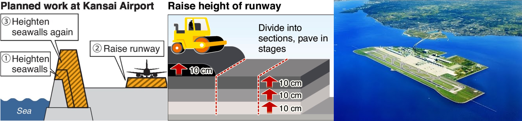
On September 4, 1994, Japan opened Kansai International Airport on an artificial island in Osaka Bay, hailed as an engineering marvel that would revolutionize airport design worldwide. The $20 billion project represented the ultimate expression of pile group foundation engineering - millions of sand drains and hydraulic columns supporting massive infrastructure loads. Yet within months, engineers discovered their foundation calculations had catastrophically underestimated reality. The airport had sunk 27 feet by 1990, during construction - 50% more than the predicted 19 feet.
The disaster unfolding beneath this engineering showcase revealed the critical flaw in pile group analysis: engineers had calculated settlement based on individual pile behavior, failing to account for the massive group interaction effects occurring across the 1,055-hectare artificial island. By 1999, the island had sunk 8.2 meters - almost 50% more than predicted. As of 2024, total settlement has reached 13.66 meters, with the airport continuing to sink 6 centimeters annually. The basic relationship that failed them was deceptively simple:
P_group ≠ n × P_single
Where P_group represents the actual group capacity and P_single is the individual pile capacity. The Kansai failure demonstrated that massive pile group installations create consolidation settlements far exceeding individual pile predictions, fundamentally challenging how engineers approach deep foundation design for large-scale infrastructure projects.
The Engineering Foundation: Understanding Pile Group Mechanics
The fundamental principle behind pile group behavior lies in the complex interaction between individual pile elements and the surrounding soil mass. Unlike isolated piles that develop their full capacity independently, piles in groups create overlapping stress zones that reduce the overall system efficiency.
When a single pile transfers load to the soil, it creates a zone of influence extending roughly 2-3 pile diameters from its centerline. This stress bulb represents the volume of soil mobilized to resist the applied loads. The governing equation for single pile capacity follows:
Q_single = Q_skin + Q_tip = α × c × A_side + N_c × c × A_tip
Where Q_skin represents skin friction capacity, Q_tip is the tip bearing capacity, α is the adhesion factor, c is soil cohesion, A_side is the pile shaft area, N_c is the bearing capacity factor, and A_tip is the pile tip area.
However, when piles are placed in groups, their individual stress zones overlap, creating a phenomenon known as the "group effect." The overlapping stress fields mean that the soil mass supporting one pile is also being stressed by adjacent piles, reducing the effective capacity of each pile in the group. This interaction is quantified through the group efficiency factor:
η = Q_group / (n × Q_single)
Where η (eta) is the group efficiency factor, Q_group is the actual group capacity, n is the number of piles, and Q_single is the individual pile capacity. This efficiency factor typically ranges from 0.6 to 1.0, meaning pile groups often carry only 60-100% of their theoretical individual capacities combined.
The physical mechanism driving this efficiency reduction involves soil displacement and stress redistribution. As each pile settles under load, it causes the surrounding soil to deform and redistribute stress to adjacent areas. In a pile group, this deformation field from multiple piles creates a composite settlement pattern that exceeds what any individual pile would experience in isolation. Think of it like a "snowshoe effect" in reverse - while snowshoes distribute weight to prevent sinking, pile groups concentrate stresses in overlapping zones, potentially causing excessive settlement.
Real-World Applications: Where Pile Groups Shape Our Infrastructure
Pile group effects dominate the foundation design of virtually every major structure in modern construction. High-rise buildings, bridges, industrial facilities, and marine structures all rely on pile groups to transfer massive loads through weak surface soils to competent bearing strata below.
In high-rise construction, pile groups supporting tower foundations typically consist of 50-200 individual piles arranged in carefully planned patterns. The Burj Khalifa in Dubai, for example, utilizes a pile group system extending 165 feet deep, where group efficiency factors significantly influenced the final design capacity. Our repository's POLEFDN.xls calculation (downloaded over 2,812 times with a 4.5-star rating), developed by community contributor Alex Tomanovich, addresses these complex design scenarios with comprehensive group analysis capabilities.
Bridge foundations present another critical application where pile group effects determine structural safety and serviceability. Highway bridge piers often utilize pile groups ranging from 6-20 piles arranged in rectangular or circular patterns. The group spacing, typically 2.5-4 pile diameters center-to-center, directly affects the efficiency factor and overall foundation capacity. Engineers must consider both vertical load capacity reduction and lateral load distribution through the pile group when designing for combined gravity and wind loads.
Industrial facilities such as power plants, refineries, and manufacturing complexes frequently require pile foundations capable of supporting equipment loads exceeding 10,000 kips. These foundations often utilize large pile groups with 30-100 piles, where group efficiency becomes a critical economic factor. Our repository's PILEGRP.xls calculation (downloaded over 1,103 times with a 4.4-star rating), provides engineers with the tools to optimize pile group layouts for maximum efficiency while maintaining safety margins.
Marine structures like piers, wharves, and offshore platforms rely heavily on pile group foundations to resist both vertical loads and significant lateral forces from waves, wind, and seismic events. These applications often involve pile groups with irregular spacing patterns dictated by structural layout requirements, making group efficiency analysis particularly complex.
The Hidden Complexity: Why Simple Addition Becomes Engineering Challenge
The apparent simplicity of pile group design - "just add more piles for more capacity" - masks a web of complex engineering challenges that have confounded designers for over a century. The primary complicating factors involve soil behavior, pile installation effects, load distribution patterns, and time-dependent changes in capacity.
Soil heterogeneity represents the first major challenge in pile group analysis. Natural soil deposits rarely exhibit uniform properties, creating varying support conditions for different piles within the same group. Clay layers may provide excellent skin friction for some piles while offering minimal support for others. Sand layers introduce different failure mechanisms and capacity calculations. The interaction between these varying soil conditions and pile group geometry creates complex stress distributions that resist simple mathematical prediction.
Installation sequence effects add another layer of complexity often overlooked in preliminary design. The order in which piles are driven significantly affects soil conditions and capacity development. Early-installed piles may experience capacity loss as subsequent pile driving densifies or disturbs surrounding soils. This phenomenon, known as "setup" or "relaxation," can cause individual pile capacities within a group to vary by 20-50% depending on installation sequence and timing.
The mathematical complexity becomes apparent when considering the full three-dimensional analysis required for accurate group behavior prediction:
K_group = f(K_individual, s/d, L/d, ρ_soil, ν_soil, installation_effects)
Δ_group = Σ(Δ_i × I_ij × q_j) for i,j = 1 to n
η_efficiency = f(pile_spacing, soil_properties, load_level, time_effects)
Where K_group represents group stiffness, s/d is spacing-to-diameter ratio, L/d is length-to-diameter ratio, ρ_soil is soil density, ν_soil is Poisson's ratio, Δ_group is group settlement, I_ij are influence factors between piles i and j, and q_j represents individual pile loads.
While these equations look intimidating on paper, our XLC add-in displays them as easily readable mathematical equations directly in Excel, transforming complex three-dimensional analyses into manageable calculation procedures that maintain the rigor required for professional design.
Load redistribution within pile groups creates additional analytical challenges. Individual piles within a group rarely carry equal loads, even when designed to do so. Variations in soil conditions, construction tolerances, and structural connectivity cause load concentrations in certain piles while others remain underutilized. This uneven load distribution affects both capacity and settlement performance, requiring iterative analysis procedures to achieve equilibrium solutions.
Professional Approach: Ensuring Pile Group Reliability
Professional pile group design requires a systematic approach that addresses capacity, settlement, and constructability while maintaining appropriate safety margins. The ExcelCalcs community shares a passion for making accurate calculations with MS Excel, providing a platform where engineers can access expert knowledge through our comments feature to navigate these complex design challenges.
Modern practice involves multiple analysis methods to verify pile group performance. The elastic analysis method treats the pile group as a composite foundation element, calculating group settlement using elastic theory and influence factors. The equivalent raft method simplifies the analysis by treating the pile group as a large shallow foundation at the pile tip level, providing conservative estimates for preliminary design. Advanced methods incorporate soil-structure interaction through finite element analysis or boundary element methods, offering detailed stress and displacement predictions.
Quality assurance protocols for pile group design emphasize verification through multiple calculation approaches. Engineers typically perform hand calculations for preliminary sizing, detailed computer analysis for final design, and independent checking through alternative methods. Load test programs on test piles and group load tests provide validation of design assumptions and calibration of analysis methods. Our repository's worked solutions give engineers a head start in establishing these verification procedures with proven calculation templates.
Professional documentation standards require clear presentation of design assumptions, analysis methods, and safety factors applied to pile group calculations. Load path diagrams showing force transfer from structure through pile cap to individual piles help reviewers understand design intent. Settlement calculations must address both immediate and long-term effects, considering consolidation of compressible layers beneath the pile group. Building on existing Excel skills with a much faster learning curve than specialized software, engineers can maintain comprehensive design documentation while ensuring calculation transparency.
The importance of peer review through the ExcelCalcs comments feature cannot be overstated in pile group design. The complexity of soil-structure interaction analysis benefits from multiple perspectives and experience-based insights. Quality assurance through collaborative review helps identify potential design issues before construction, reducing the risk of field problems and costly remediation.
Repository Showcase: Comprehensive Pile Group Solutions
Beyond our flagship PILEGRP.xls analysis, engineers can access specialized calculations including POLEFDN.xls (2,812 downloads, 4.5-star rating), AXIAL AND LATERAL LOAD PILES (FEM) (1,037 downloads, 4.2-star rating), and Bored Piles For The Analysis of Layered Soil.xlsx for complex geotechnical conditions (959 downloads, 4.4-star rating).
For specialized applications, our repository includes Machine Foundation Analysis and Design (687 downloads, 4.4-star rating), US Steel Sheet Pile Design for marine applications (570 downloads, 3.5-star rating), and Pile Capacity Calculation (567 downloads, 4.1-star rating). International practitioners can utilize calculations designed for various national codes and standards, while bridge engineers can access specialized tools for highway and railway applications. This diversity ensures that regardless of your local code requirements or specific design challenges, our community has developed solutions to meet your pile group analysis needs.
The repository also features advanced calculations for Bored Piles Wall and Ground Anchors (743 downloads, 4.4-star rating), Analysis of a sheet pilewall.xls (539 downloads, 3.8-star rating), and SOIL SPRING CONSTANTS FOR FOUNDATIONS (445 downloads, 4.3-star rating) for dynamic analysis applications.
Start Your Pile Group Design Journey Today
Whether you're designing foundations for skyscrapers or analyzing existing pile groups for capacity upgrades, our PILEGRP.xls calculation provides the comprehensive analysis tools you need. With over 1,103 downloads and a 4.4-star community rating, this calculation template represents proven engineering analysis trusted by professionals worldwide.
We thank Alex Tomanovich and our entire community of contributors who have developed these essential foundation design tools through years of professional practice and collaborative refinement. Their expertise, combined with peer review through our comments system, ensures that every calculation template meets the highest standards of technical accuracy and practical applicability.
Join the ExcelCalcs community today with a $99 annual professional subscription - insignificant compared to MathCAD, Mathematica, or Maple - and gain access to our complete repository of pile foundation analysis tools. Students and educators benefit from our 50% academic discount, while free trials allow you to experience the power of professional calculation templates before committing. Discover why thousands of engineers trust our templates for their most critical pile group design challenges.
Because when the ground beneath your structure matters most, you need calculations that account for every interaction.